The 2004, 2005, 2006, 2007, 2008, 2009, 2011, 2012, 2013, and 2014 Honda Elysion 1G was produced with various engines and modifications. During this time, the model was modernized twice. In our article, you will find a description of the Honda Illusion 1G fuses and relays, along with diagrams of the fuse blocks and their locations. Pay attention to the cigarette lighter fuse.

Passenger lounge
In the cabin, the fuse box is located under the dashboard, on the driver’s side.
Photo example
Check the consistency of the task with the diagrams on the block covers.
Block cover diagram.
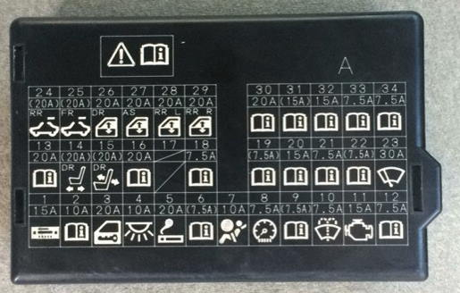
Diagram
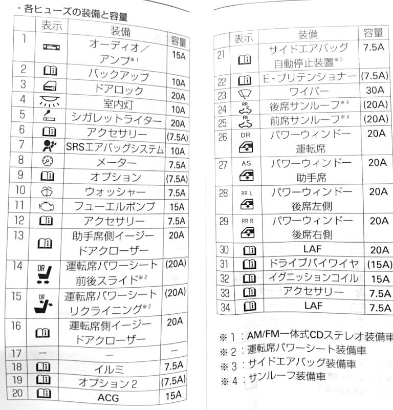
Marking
- 15A Audio/Amplifier
- 10A Reserve
- Central locking 20A
- 10A Interior lighting
- 20A Car Cigarette Lighter
- 7.5 Additional power source
- SRS 10A System
- 7.5A Tools
- Option 7.5A
- 7.5A washer
- 20A Fuel Pump
- Additional 7.5A power supply
- 20A electric chair
- 20A electric driver’s seat with height adjustment
- 20A Height adjustment (rear)
- 20A Passenger Seat Power Supply
- Option
- Lighting 7.5A
- Ignition 15A
- Generator 15A
- 7.5A Auto lock
- Tensioner 7.5A
- 30A Windshield wiper
- 20A Rear Cover
- 20A Front flap
- Driver’s window actuator 20A
- 20A Passenger’s Electric Window Motor
- 20A Rear left electric window drive
- 20A Rear right electric window drive
- 20A LAF
- 15A Wired Control
- Ignition coil 15A
- 7.5A accessories
- 7.5A LAF
In the case of a car cigarette lighter, fuse No. 5 is responsible for a current of 20A.
Engine compartment
Fuse and relay block
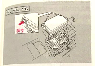
Under the hood, in the engine compartment, the main unit with fuses and relays can be located on the left or right side, depending on the engine displacement.
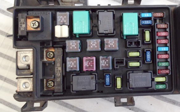
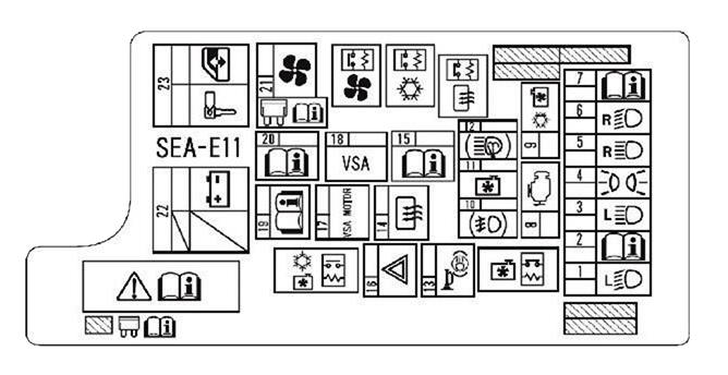
Diagram
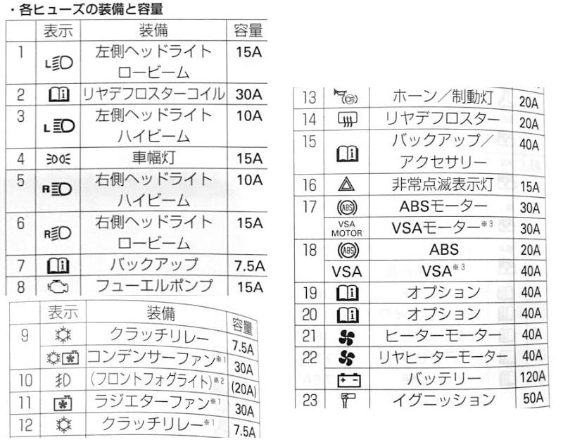
Location
| 1 | 10A Left headlight (low beam) |
| 2 | 30A Heated rear window |
| 3 | 10A Left headlight (high beam) |
| 4 | 15A Side marker light, dashboard light, interior light, glove box light, license plate light, selector position light |
| 5 | 10A Right headlight (high beam) |
| 6 | 10A Right headlight (low beam) |
| 7 | 7.5A Reversing lights |
| 8 | 15A Camshaft Position (CMP) Sensor B, Crankshaft Position (CKP) Sensor, Engine Control Module (ECM/PCM), Idle Air Control Valve (IAC), Injectors, Mass Air Flow Sensor, Engine Control Module (PGM-FI) Relay, Data Link Connector (DLC), Throttle Relay |
| 9 | Air Conditioner Fan 20A, Air Conditioner Fan Relay |
| 10 | 20A Fog light |
| 11 | 20A Cooling Fan, Cooling Fan Relay |
| 30A Cooling Fan, Cooling Fan Relay | |
| 12 | 7.5A A/C Compressor Clutch, A/C Compressor Clutch Relay |
| 30A Headlight Washer Control Unit | |
| 13 | 20A brake light, ABS/TCS (’03-’05), Vehicle Stability Assist (VSA) (’06-’07), Engine Control Module (ECM/PCM), Additional brake light, Key switch indicator, Electronic Control Unit (MICU), Horn |
| 14 | 40A Heated Rear Window, AM/FM Antenna Booster, Heated Rear Window Relay |
| 15 | 40A fuses (internal fuse box): No. 5, 6, 7, 8, 9; fuse (engine compartment fuse block): No. 7 |
| 16 | 15A Turn Signal and Alarm Relay |
| 17 | 30A ABS/TCS or Vehicle Stability Control (VSA) |
| 18 | 20A ABS/TCS |
| 40A Vehicle Stability Assist (VSA) | |
| 19 | 40A Fuses (Internal Fuse Block): No. 1, 2, 3, 4 |
| 20 | 40A fuses (internal fuse box): No. 12, 14, 15, 16, 17 |
| 21 | 40A heater, heater relay |
| 22 | Rear Heater Fan Motor 40A |
| 120A Main Fuse / Battery | |
| 23 | 50A Ignition Switch |
| 50A power window relay. Fuses (internal fuse box): No. 24, 25, 26, 27, 28 | |
| Relay | |
| R1 | Engine cooling fan |
| R2 | Air conditioner fan |
| R3 | Heated rear window |
| R4 | Air conditioning compressor clutch |
| R5 | Heater |
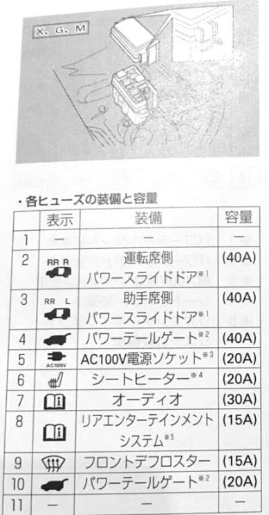
Fuse block
Type 1
Diagram
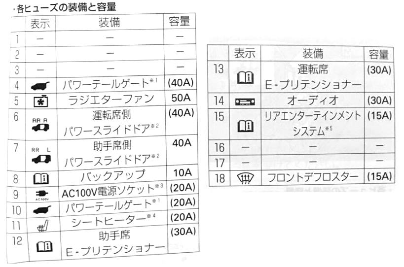
Type 2
If you have anything to add, please write in the comments.