The 10th-generation Honda Civic was produced in 2016, 2017, 2018, 2019, 2020, and 2021 in sedan, hatchback, and coupe versions and was available worldwide. During this time, the model underwent a facelift. Our article describes the 10th-generation Honda Civic fuses and relays, including block diagrams, locations, and sample photos. Pay attention to the cigarette lighter fuse.
The fuse and relay labels in your blocks may differ from those shown. Check your schematics for component labels.
Cabin block
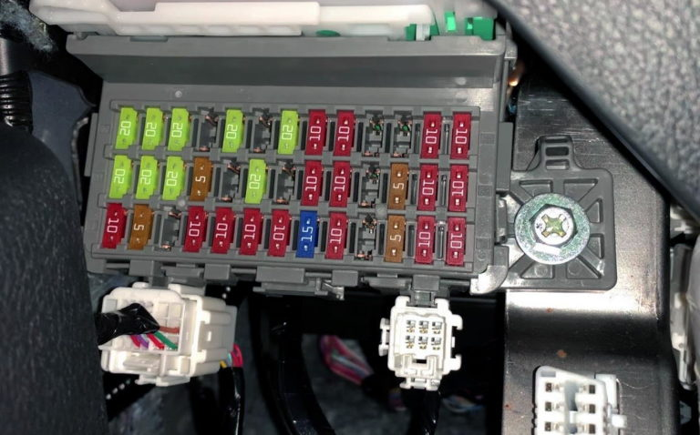
In the cabin, the main fuse box is located under the dashboard on the driver’s side. The diagnostic connector is also located there.
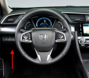
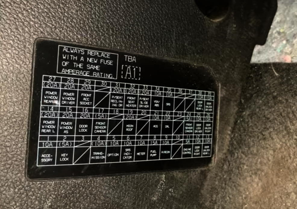
The original diagram of your car will be located on the shelf under the dashboard, by the driver’s left foot.
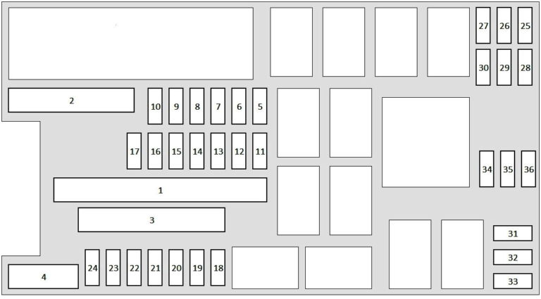
Diagram
Description
| 1 | 10 Accessories |
| 2 | 5A Key lock |
| 3 | – |
| 4 | 5/10A Front sensor camera, gearbox |
| 5 | Option 10A |
| 6 | SRS 10A indicator |
| 7 | 10A devices |
| 8 | 15A Fuel pump |
| 9 | 10A Air Conditioner |
| 10 | − |
| 11 | 10A Motor Control |
| 12 | 10A Passenger door lock |
| 13 | 10A Driver’s side rear door unlock |
| 14 | 20A Driver’s side rear window lifter |
| 15 | 20A Front passenger window regulator |
| 16 | Lock 20A |
| 17 | 5/10A gearbox, front sensor camera |
| 18 | − |
| 19 | Manhole 20A |
| 20 | − |
| 21 | 10A ACG (ignition) |
| 22 | 10A Daytime running lights |
| 23 | − |
| 24 | 5A Front Sensor Camera |
| 25 | 10A Driver’s door lock |
| 26 | 10A Passenger door unlock |
| 27 | 20A Rear passenger window regulator |
| 28 | 20A Driver’s window lifter |
| 29 | 20A front accessory socket, cigarette lighter |
| 30 | 10A Smart Input |
| 31 | 20A Driver’s seat with electric tilt adjustment |
| 32 | 20A Front seat heating |
| 33 | 20A Power-adjustable driver’s seat |
| 34 | 10A VSA/ABS |
| 35 | 10A SRS |
| 36 | − |
| 37 | − |
| 38 | 10A Driver’s side rear door lock |
| 39 | 10A Driver’s door unlock |
Fuse no. 29 with a current of 20A is responsible for the cigarette lighter.
Block under the hood
Under the hood, on the left side, there is a main unit with fuses and relays, covered by a protective cover.
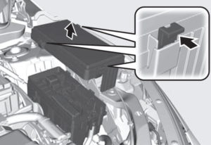
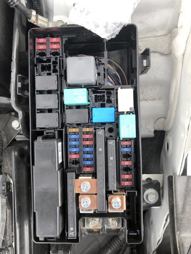
The block itself will look something like this.
Block cover diagram
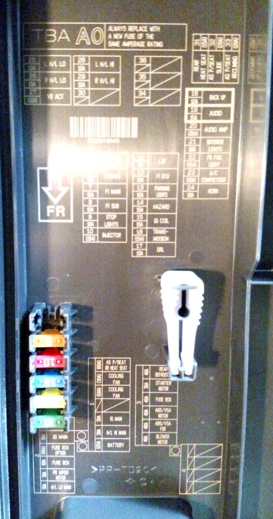
Marking
| 1 | 60A Electric Passenger/Rear Seat Heating |
| Cooling fan 30A | |
| 50A cooling fan | |
| – | |
| Chief Inspector | |
| – | |
| 30A high beam | |
| 125A battery | |
| 2 | 70A EPS |
| 30A IG Home | |
| 50A | |
| Option 40A (fuse blocks) | |
| 60A fuse block | |
| Front wiper motor 30A | |
| 30A Low beam headlights | |
| 3 | 40A Rear De-icer |
| 30A starter | |
| – | |
| 40A fuse block | |
| 40A ABS/VSA motor | |
| 40A ABS/VSA FSR | |
| 40A fan motor | |
| 4 | – |
| 5 | 5A Cooling fan |
| 6 | Washer 15A |
| 7 | 15A Main fuel injection |
| 8 | 15A Fuel injection sub-assembly |
| 9 | 10A Stop signals |
| 10 | Injector 15A |
| 11 | 5A LAF |
| 12 | 10A Engine Controller |
| 13 | 10A Parking lights |
| 14 | 15A Emergency Alarm |
| 15 | 15A IG coil |
| 16 | 15A Transmission |
| 17 | 10A Daytime running lights |
| 18 | 10A Reversing light |
| 19 | 15A Sound |
| 20 | 30A audio amplifier |
| 21 | 10A Interior lighting |
| 22 | 15A Front fog lights |
| 23 | 10A Air Conditioner Compressor |
| 24 | Signal 10A |
| 25 | 10A Left low beam |
| 26 | 10A Right low beam |
| 27 | 10A VB ACT |
| 28 | 10A Left high beam |
| 29 | 10A Right high beam |
| 30 | – |
| 31 | 15A Rear seat heaters |
| 32 | 20A Power passenger seat |
| 33 | 20A electric reclining passenger seat |
| 34 | – |
| 35 | – |
| 36 | – |