The 9th-generation Honda Civic was produced in 2012, 2013, 2014, and 2015 in various body styles: sedan, coupe, hatchback, and wagon. This article will describe the fuses and relays in the 9th-generation Honda Civic, along with block diagrams, locations, and photo examples of their use. Let’s focus on the cigarette lighter fuse.

American sedans and coupes and European hatchbacks and station wagons differed significantly in both general layout and technical content, so the purpose of the fuses and relays in the blocks may differ from that shown.
Cabin block
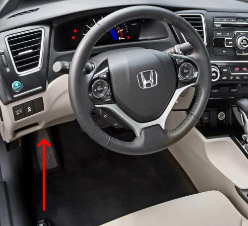
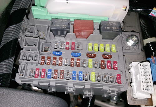
In the cabin, the main unit with fuses and relays is located under the dashboard on the driver’s side.
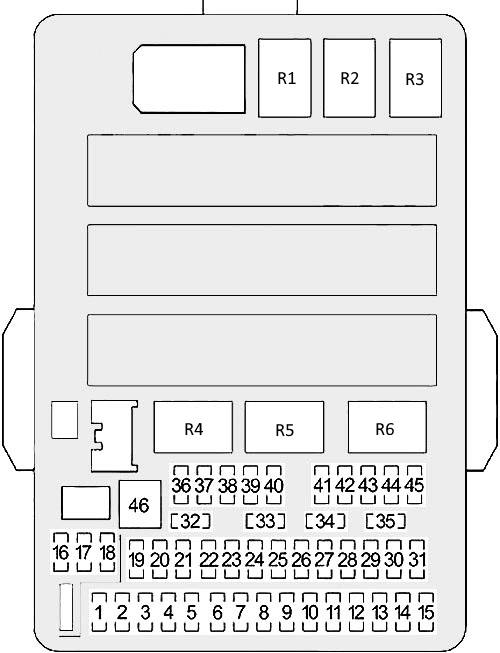
Description
| 1 | 20A NAS (Hitch Assist System) |
| 2 | 10A ACG (ignition) |
| 3 | 10A SRS |
| 4 | 15A Fuel pump |
| 5 | 7.5A devices |
| 6 | 7.5A Window regulator |
| 7 | 15A VB SQL |
| 8 | Door lock motor 15A 2 (unlock) |
| 9 | Door lock motor 15A (unlock) |
| 10 | 10A Outdoor daylighting |
| 11 | 20A Luke |
| 12 | 15/20A accessory socket (center console) |
| 13 | 20A Electric Seat Drive |
| 14 | 15A Seat Heaters |
| 15 | 10A Driver’s door lock motor (unlock) |
| 16 | – |
| 17 | – |
| 18 | – |
| 19 | 7.5A AC |
| 20 | 7.5A ACC key lock |
| 21 | 7.5A Daytime running lights |
| 22 | 7.5A HAC |
| 23 | 7.5A HAC |
| 24 | 7.5A ABS/VSA |
| 25 | 7.5A AC |
| 26 | – |
| 27 | 15/20A auxiliary power socket (front), car cigarette lighter |
| 28 | Washer 15A |
| 29 | 7.5A ODS |
| 30 | 10A Driver’s door lock motor (lock) |
| 31 | 10A Smart |
| 32 | Door lock motor 15A 2 (lock) |
| 33 | 15A Door Lock Motor 1 (Lock) |
| 34 | 7.5A Small Lamps (Dimensions) |
| 35 | Lighting 7.5A |
| 36 | Book |
| 37 | 20A Electric Seat Drive |
| 38 | 10A Left high beam |
| 39 | 10A Right high beam |
| 40 | 7.5A Rear fog light |
| 41 | Lock 20A |
| 42 | 20A Driver’s window lifter |
| 43 | 20A Rear passenger window regulator |
| 44 | 20A Front passenger window regulator |
| 45 | 20A Driver’s side rear window lifter |
| 46 | 30A Windshield wiper |
| – | 7.5A STS |
| R1 | Power window relay |
| R2 | Fuel pump relay |
| R3 | Starter relay |
| R4 | |
| R5 | Fuel injection relay |
| R6 | Power window relay |
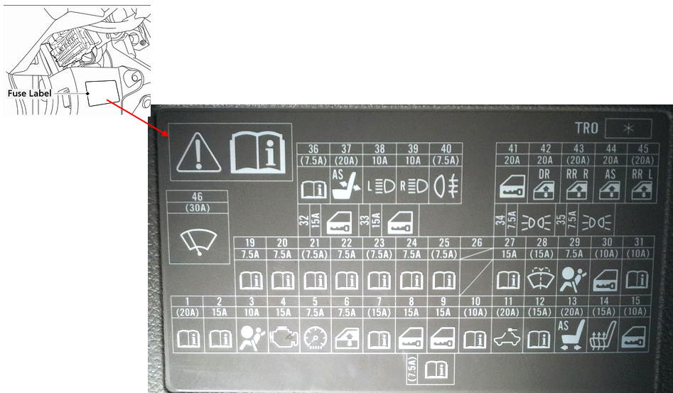
Check the element symbols on the diagrams.
Example of a diagram with notation
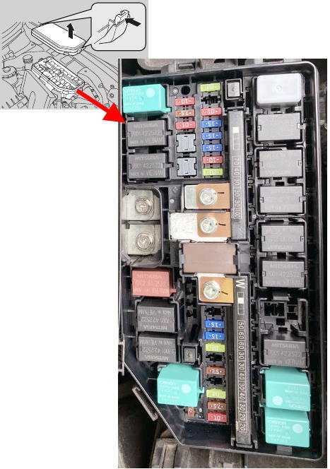
Block under the hood
Under the hood, on the left side, there is a main unit with fuses and relays, covered by a protective cover.
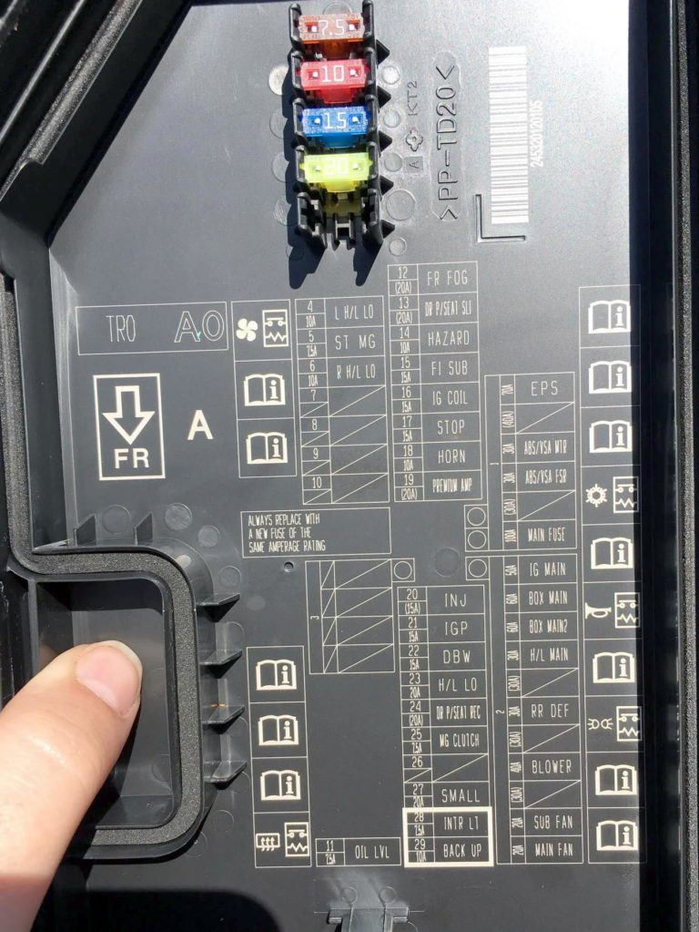
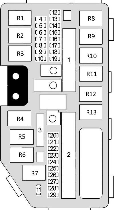
Meeting
| 1 | 70A EPS (power steering) |
| 30A ABS/VSA motor | |
| 30A ABS/VSA FSR | |
| 30A cleaning motor | |
| 100A Main Fuse | |
| 2 | 30/50A IG main |
| 60A main fuse block | |
| 60A Main Fuse Block 2 | |
| 30A Main Headlight Fuse | |
| ST/MG 30A switch | |
| 30 Rear heating | |
| 30A IG Main 2 | |
| Fan 40A | |
| 20F Auxiliary Fan Motor | |
| 20F Main Fan Motor | |
| 3 | – |
| 4 | 15A Left dipped beam |
| 5 | 7.5A ST DIAG/ST MG |
| 6 | 15A Right low beam headlight |
| 7 | – |
| 8 | – |
| 9 | – |
| 10 | – |
| 11 | 7.5A Oil level |
| 12 | 20A Fog lights |
| 13 | 20A Power-adjustable driver’s seat |
| 14 | 10A Emergency Alarm |
| 15 | 15A FI Sub (injection) |
| 16 | Ignition coil 15A IG |
| 17 | 15A Stop signals |
| 18 | 10A Audible signal |
| 19 | 20A Trailer Electrical Equipment |
| 20 | 15A Right headlight low beam injector |
| 21 | 15A IGP |
| 22 | 15A DBW |
| 23 | 15A Left dipped beam |
| 24 | 20A Driver’s seat with electric tilt adjustment |
| 25 | 7.5A clutch |
| 26 | Washer 15A |
| 27 | 20A Side marker lights |
| 28 | 7.5A Interior lighting |
| 29 | 10A Reversing light |
| R1 | Heater fan relay |
| R2 | Starter relay 1 |
| R3 | Auxiliary fan relay |
| R4 | Ignition coil relay |
| R5 | Starter relay 2 |
| R6 | Injection system relay |
| R7 | Rear heater relay |
| R8 | Fan speed relay (high/low) |
| R9 | Head fan relay |
| R10 | Slag cleaning relay |
| R11 | Magnetic clutch relay |
| R12 | Front fog light relay |
| R13 | Horn relay |