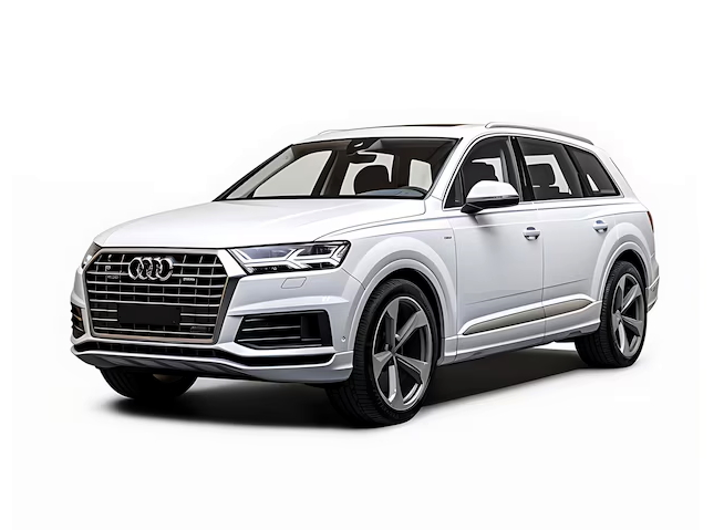
The second-generation Audi Q7 was produced in 2016, 2017, 2018, 2019, 2020, 2021, 2022, 2023, 2024, and 2025. During this time, the model underwent several facelifts. This article will provide information describing the Audi Q7 2G fuses, along with diagrams of the fuse blocks, their locations, and sample photos. Note the cigarette lighter fuse.
Passenger lounge
Left fuse box
At the left end of the dashboard, behind the protective cover, is the fuse box.
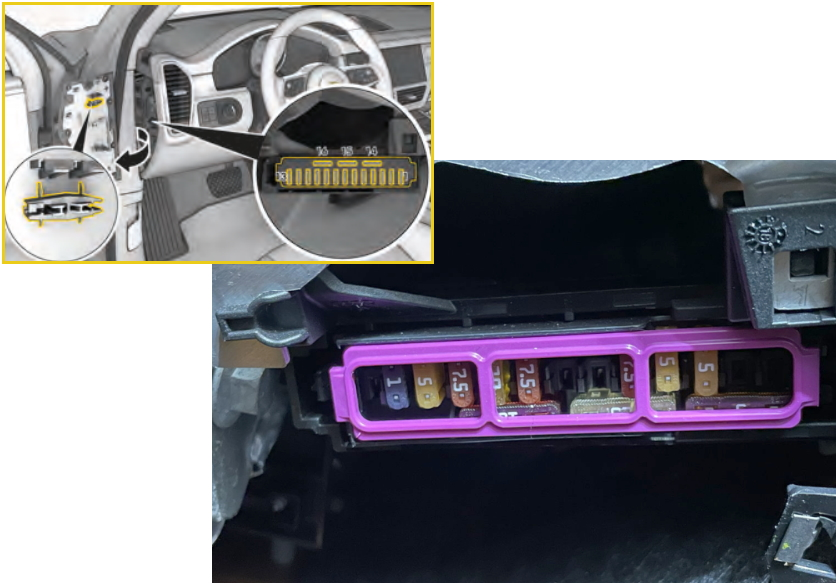
Diagram
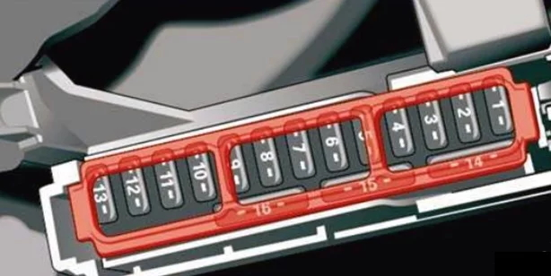
| 1 | – |
| 2 | Audi telephone booth, communication antenna |
| 3 | Air conditioning system, aromatization system |
| 4 | Projection display |
| 5 | Audi Music Interface, USB port |
| 7 | Steering column lock |
| 8 | Top/bottom display |
| 9 | Combination of instruments |
| 10 | DVD drive |
| 11 | Light switch, switch panels |
| 12 | Steering column electronics |
| 13 | Volume control |
| 14 | MMI infotainment control module |
| 15 | Steering column adjustment |
Fuse box in the footwell
Left-hand drive cars
To access the device, you must remove the protective cover. Use a flat-blade screwdriver to remove the mounting screw cover, then unscrew the screw and remove the cover.
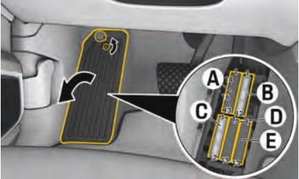
The fuse block itself will look something like this.
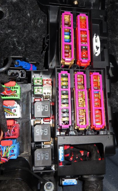
Diagram
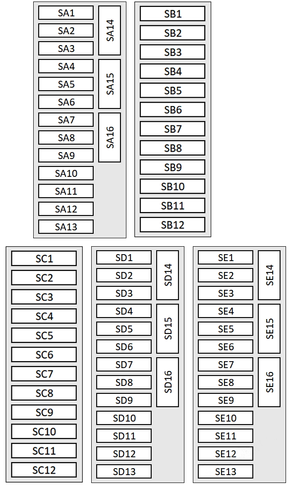
General designation
| SA fuse panel (brown). | |
| A1 | Catalytic converter heating, camshaft adjustment. |
| A2 | Airflow sensor, heated oxygen sensors |
| A3 | Engine heater, fuel injectors, exhaust doors |
| A4 | Hot water pump, exhaust door, NOX sensor, particulate sensor, biodiesel sensor |
| A5 | Brake light sensor |
| A6 | Engine valves |
| A7 | Heated oxygen sensor, air flow sensor |
| A8 | High pressure pump, engine mount |
| A9 | Engine components, engine relays |
| A10 | Oil pressure sensor, oil temperature sensor |
| A11 | Coolant pump 48V, starter-generator 48V, starter-generator 12V |
| A12 | Engine valves |
| A13 | Engine cooling |
| A14 | Powertrain control module |
| A15 | Heated oxygen sensors |
| A16 | Fuel pump |
| SB fuse panel (red) | |
| B1 | Ignition coils |
| B3 | 48V heater |
| B4 | Electric compressor |
| B5 | Engine mount |
| B6 | Windshield washer control module |
| B7 | Panel |
| B8 | Air conditioning fan |
| B9 | Driver assistance system control module |
| B10 | Emergency call and communication control module |
| B11 | Engine start, electric clutch |
| B12 | Right headlight |
| SC fuse panel (black) | |
| C1 | Heated front seats |
| C2 | Wipers |
| C3 | Left headlight electronics |
| C4 | Panoramic glass roof |
| C5 | Left front door control module |
| C6 | Sockets (cigarette lighter) |
| C7 | Rear right door control module |
| C8 | Left headlight |
| C9 | Right headlight electronics |
| C10 | Windshield/Headlamp Washer Control Module |
| C11 | Left rear door control module |
| C12 | Autonomous heater |
| SD fuse panel (brown) | |
| D1 | Seat ventilation, seat electronics, rear-view mirror, rear climate control panel, diagnostic connector, traffic information antenna (TMC) |
| D2 | On-board network control module, diagnostic interface |
| D3 | Sound generator |
| D4 | Transmission fluid cooling valve |
| D5 | Engine starting, electric drive |
| D8 | Night Vision Assist, Active Roll Stabilization |
| D9 | Adaptive cruise control, front wheel sensors |
| D10 | External sound generator |
| D11 | Cross Traffic Assist, Driver Assistance Systems |
| D12 | Right headlight |
| D13 | Left headlight |
| D15 | USB connection |
| D16 | Getting ready for backseat entertainment |
| SE fuse panel (red) | |
| E1 | Anti-theft alarm |
| E2 | Engine control module |
| E3 | The front seats are electric, with lumbar support |
| E4 | Automatic transmission gear shift lever |
| E5 | Horn |
| E6 | Handbrake |
| E7 | Diagnostic interface |
| E8 | Roof electronics control module |
| E9 | 48V starter-generator |
| E10 | Airbag control module |
| E11 | Electronic Stability Control (ESC), Anti-lock Braking System (ABS) |
| E12 | Light/rain sensor diagnostic connector |
| E13 | Climate control system |
| E14 | Front right door control module |
| E15 | Air conditioning compressor |
Additional safety elements can be installed near the fuse box.
Model
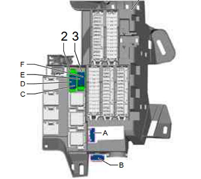
Choice
- A – 15A Seat and steering column adjustment control unit with memory
- B – 15A Front passenger seat adjustment with memory unit
- C – 40A ABS Control Unit
- D – 40A ABS Control Unit
- E-
- F-50A Auxiliary Gearbox Hydraulic Pump
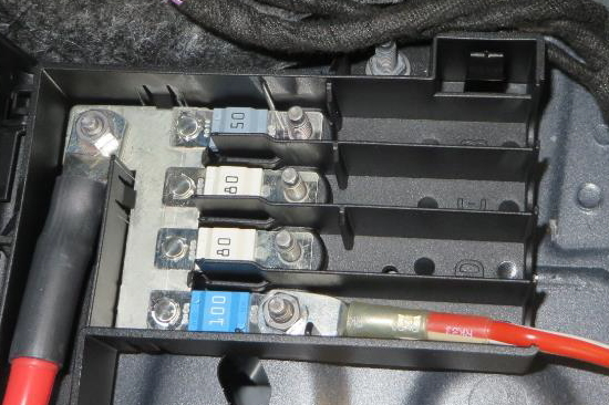
A large capacity fuse block can be mounted near the battery.
Photo – example
Trunk
In the trunk on the left side, under the protective cover, there is another box with fuses and relays.
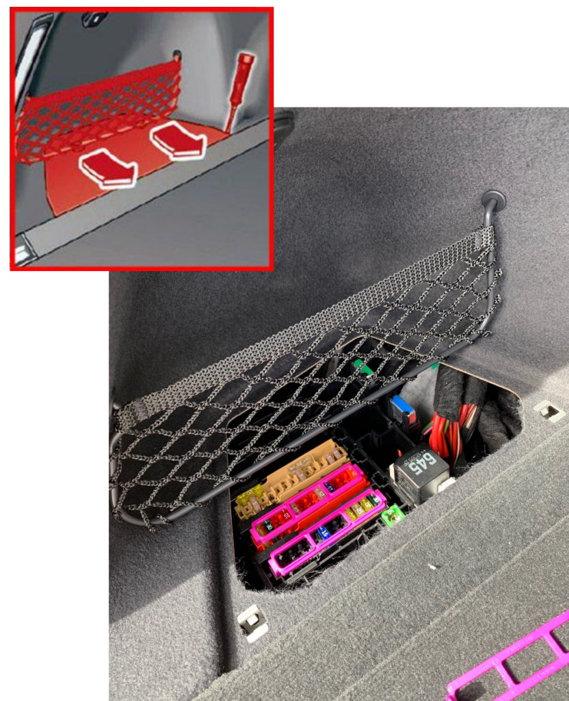
Diagram
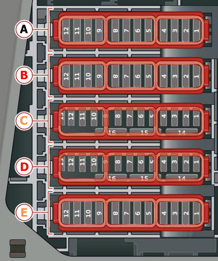
Choice
| Fuse panel A (black) | |
| A1 | High voltage heating, temperature control |
| A5 | Air Suspension/Suspension Control |
| A6 | Automatic transmission control module |
| A7 | Heated rear seats, rear air conditioning |
| A8 | Third row seat adjustment |
| A9 | Comfort rear light control unit, left rear light |
| A10 | Driver’s side front seat belt pretensioner |
| A11 | Central locking of the trunk lid, fuel filler flap, trunk lid |
| A12 | Trunk lid control module |
| Fuse panel B (red) | |
| B1 | Rear air conditioning fan |
| B2 | Sound amplifier |
| B3 | Exhaust system cleaning, sound drive |
| B4 | Rear air conditioning control panel |
| B5 | Right tow hook light |
| B6 | Trailer hitch positioning motor |
| B7 | Unlocking the coupling device |
| B8 | Left tow hook |
| B9 | Hitch socket |
| B10 | Allroad sports differential |
| B11 | Exhaust gas purification |
| B12 | Driver’s side rear seat belt pretensioner |
| Fuse panel C (brown) | |
| C1 | Driver assistance system control module |
| C2 | Audi telephone module |
| C3 | Front seat electronics, right lumbar support Right lumbar support |
| C4 | Side assistant |
| C5 | Preparing the rear-seat entertainment system |
| C6 | Tire pressure monitoring system |
| C7 | External antenna |
| C8 | Autonomous radio heating, tank module |
| C10 | TV tuner, data exchange module and telematics control |
| C11 | Convenient access control and startup authorization module |
| C12 | Garage door opening |
| C13 | Reversing camera, peripheral cameras |
| C14 | Right rear light comfort system control unit |
| C15 | Rear passenger seat belt pretensioner |
| C16 | Front passenger seat belt pretensioner |
| Fuse panel D (red) | |
| D1 | Active roll stabilization |
| D2 | High voltage battery |
| D3 | High voltage battery coolant pump |
| D4 | Power electronics control module |
| D5 | Brake servo |
| D6 | Voltage transformer |
| D7 | Starting the engine |
| D8 | Air conditioning compressor |
| D9 | Auxiliary battery control module |
| D10 | High voltage battery |
| D11 | Charging system |
| D12 | Radio for additional heating and air conditioning |
| D14 | Temperature control, coolant pumps |
| D15 | Thermal control module |
| Fuse panel E (brown) | |
| E7 | Heated front seats |
| E9 | Exhaust gas purification |
| E10 | Heated rear seats, rear air conditioning |
Additional elements
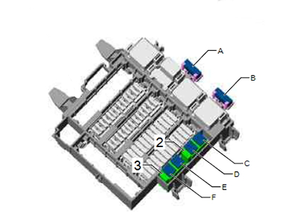
Meeting
- A – 15A Front passenger seat adjustment with memory control unit (right-hand drive)
- B –
- C – 30A Rear window heating relay
- D-40A Adaptive Suspension Compressor Electronics
- E-
- F –
If you know how to improve the material, please write in the comments.