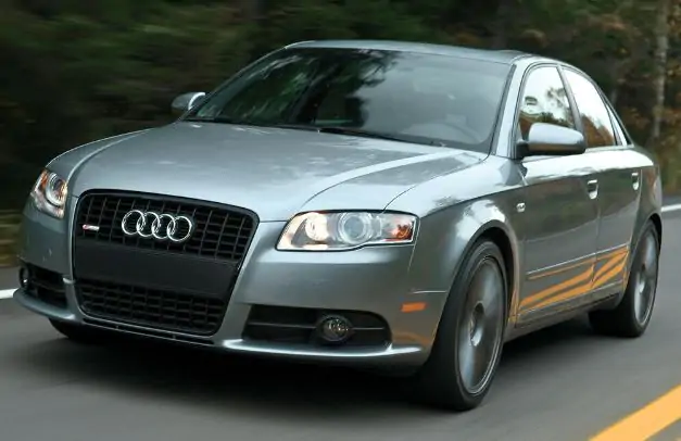
The Audi A4 B7 is the third generation of the Audi A4. It was produced in 2004, 2005, 2006, and 2007. This article presents relay and fuse block diagrams for the Audi A4 B7, along with a description of the functions of each component. The fuse for the cigarette lighter is marked.
Fuse descriptions may vary depending on the vehicle’s year of manufacture, configuration, and engine type. For the current fuse assignment, refer to your vehicle’s owner’s manual and the rear of the fuse box cover at the end of the dashboard.
Fuse and relay boxes in the passenger compartment
Main board with fuses for Audi A4 B7
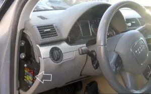
This block is located on the left side of the dashboard, behind a plastic cover.
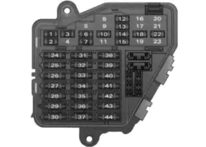
Deciphering the Scheme
| NO. | Intention |
| 1 | 10A air conditioning |
| 2 | 5A Footwell lighting |
| 3 | 5A Windshield washer nozzles |
| 4 | Fan 5A |
| 5 | 10A telephone, engine oil level sensor, multi-function switch, heated rear seats, rear window blind, automatic transmission |
| 6 | 5A Air conditioning (air quality sensor), pressure sensor |
| 7 | 10A Electronic Stability Program (ESP), brake light switch, clutch pedal sensor, steering angle sensor |
| 8 | Phone 5A |
| 9 | 15A brake booster (vacuum pump) |
| 10 | 5A automatic headlight range adjustment. Adaptive cornering lights (right) |
| 11 | absent |
| 12 | 10A diagnostic socket |
| 13 | Steering Column Module 10A |
| 14 | 10A brake light |
| 15 | 10A Instrument cluster, navigation system |
| 16 | 5A garage door opener |
| 17 | 10A Parking aid, level control, tire pressure monitoring, rain/light sensor |
| 18 | 5A Adaptive cornering light left |
| 19 | 15A fog lights |
| 20 | absent |
| 21 | absent |
| 22 | 15A Driver/Passenger Door |
| 23 | 15A Rear door |
| 24 | 20A comfortable electrical equipment with central control |
| 25 | Heater fan 30A |
| 26 | 30A heated rear window |
| 27 | 30A trailer socket (control unit) |
| 28 | 20A Fuel Pump, Diesel Auxiliary Pump |
| 29 | absent |
| 30 | 20A tilt and slide roof panel |
| 31 | 15A automatic transmission, diagnostic socket, automatically retractable interior mirror |
| 32 | 20A trailer socket |
| 33 | 15A car cigarette lighter |
| 34 | 15A is missing |
| 35 | 20A socket in the trunk |
| 36 | 30A Windshield wiper |
| 37 | 30A Windshield Washer and Headlight Cleaning Pump |
| 38 | 15A comfortable electrical installation with central control and trunk opening |
| 39 | 20A Radio System |
| 40 | Horn 25A |
| 41 | 30A autonomous heating |
| 42 | 25A Electronic Stability Program (ESP) |
| 43 | 15A motor control |
| 44 | 35A seat heating |
Fuse no. 33 with a current of 15A is responsible for the cigarette lighter.
Fuse and relay boxes under the dashboard
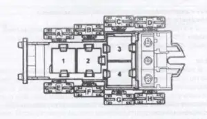
Intention
| 1 | |
| 2 | |
| 3 | |
| 4 | Control unit 3 Taxi alarm system Hands-free system |
| AND | |
| B | Optional equipment |
| C | |
| D | |
| H | (50A) Anti-lock Braking System (ABS) |
| G | (40A/60A) Cooling fan motor control unit 1 |
| F | (10A) Official vehicles |
| me | Cooling fan motor control unit 2 – if equipped |
2-block diagram
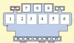
Description of the fuse diagram
| 1 | Fuel pump relay – petrol |
| 2 | Power steering control unit (Servotronic) (if installed) |
| 3 | Horn relay (dual tone) |
| 4 | Brake booster vacuum pump relay (if equipped) |
| 5 | |
| 6 | Auxiliary ignition relay |
| 7 | |
| 8 | |
| 9 | |
| F1 | |
| F2 | (10A) Rear window sunshade motor thermal fuse |
| F3 | |
| F4 | (30A) Rear electric windows thermal fuse |
| F5 | (10A) Electric seats (lumbar support adjustment) |
| F6 | (30A) Front electric windows thermal fuse |
| F7 | (30A) Trailer electrical connection |
3-block diagram
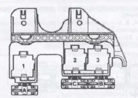
Intention
| 1 | — |
| 2 | Coolant Heater Relay 2 – High Performance |
| 3 | Coolant Heater Relay 1 – Low Power |
| F1 | (30A) Auxiliary heating – 2003 |
| F2 | (40A) Coolant Heater |
| F3 | (60A) Coolant Heater |
Fuse box in the engine compartment of an Audi A4 B7
General scheme
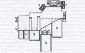
This unit is located under the ECM/TCM module (battery section). Several decoding options are available.
Description of petrol engines
| 1 | Coolant heater relay (V6) |
| 2 | Relay control (Multitronic) |
| 3 | Exhaust air pump relay |
| 4 | Coolant pump motor control unit (AMM/BDV) |
| 5 | Start Lock Switch Relay (if installed) |
| F1 | (15A) Engine management system, brake light switch (brake pedal position sensor) |
| F2 | (40A) Exhaust pump motor |
| F3 | (15A) Automatic gearbox control (6-speed automatic gearbox/Multitronic) |
Description of diesel engines
| 1 | Fuel pump relay |
| 2 | Relay control (Multitronic) |
| 3 | Glow plug relay |
| 4 | Engine control relay |
| 5 | Starter lock switch relay/reverse light relay (Multitronic) |
| F1 | (15A) Engine management system, brake light switch (brake pedal position sensor) |
| F2 | (60A/80A) Glow plugs |
| F3 | (15A) Automatic gearbox control (6-speed automatic gearbox/Multitronic) |
| F4 | (60A) Glow plugs |
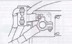
Main battery fuse