The Audi A1 (body code 8X) is a subcompact car introduced in September 2010. It is still in production. Sales of the electric Audi A1 e-tron with a 50 km range began in 2011. Our material contains information on the location and description of fuses and relays in the Audi A1. The block layout also applies to the 5-door and Sportback versions.

Fuse box inside
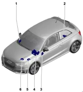
- Fuse box D -SD- ;
- Fuse holder A -SA- ;
- Fuse block C -SC- ;
- Relay/Fuse Holder F -SF- ;
- Fuse box B -SB- , fuse box H -SH- ;
- Fuse box B -SB- .
Please note that the diagram may vary depending on vehicle configuration and model year! Please refer to the description on the back of the protective cover.
Fuse Block – No. 1
Plan
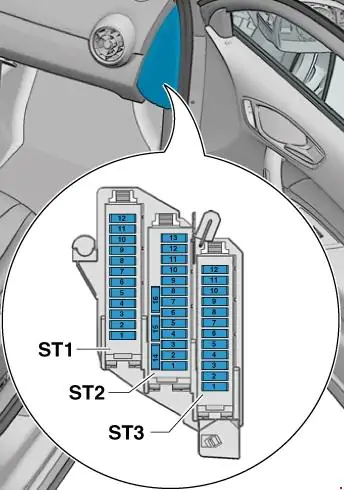
ST1 panel (black)
| 1 | 7.5 | Steering column lock control unit -J764- |
| 2 | 20 | Trailer Detection Control Unit -J345- |
| 3 | 20 | Trailer Detection Control Unit -J345- |
| 4 | 30 7.5 | Mechatronics for the dual-clutch gearbox -J743-, up to October 2014. Control unit for the electronic damping regulation -J250-, from January 2014. |
| 5 | 30 | Headlight washer relay -J39- Headlight washer pump -V11- |
| 6 | 5 | Vehicle Tracking System Interface Control Unit -J843- |
| 7 | 7.5 | Access and Start Control Unit -J518- |
| 8 | 15 | Mechatronics for dual-clutch gearbox -J743-, until October 2014 |
| 9 | 20 | Sliding roof motor -V1- |
| 10 | 7.5 | Gear shift lever sensor control unit -J587- |
| 11 | 15 | Engine electronics power supply relay -J757- , up to October 2014 Fuel pressure control valve -N276- , up to October 2014 |
| 12 | – | Unused |
ST2 panel (brown)
| 1 | 5 | Reversing light switch -F4- Gear shift lever sensor control unit -J587- Dual clutch gearbox mechatronics module -J743- |
| 2 | 10 | High pressure sensor -G65- Engine oil level and temperature sensor -G266- Air conditioning control unit -J301- Socket relay -J807- Automatically dimming interior rear view mirror -Y7- 16-pin connector -T16-, diagnostic connector |
| 3 | 5 | Data bus diagnostic interface -J533- |
| 4 | 5 | Heating control unit -J65- Structure -borne sound control unit -J869- |
| 5 | 7.5 | Light switch -E1- Starter relay 1 -J906- Voltage regulator -J532- Starter relay 2 -J907- Automatic dimming interior mirror relay -J910- Left front headlight -MX1- Right front headlight -MX2- |
| 6 | 5 | Light switch -E1- |
| 7 | 5 | ABS control unit -J104-, up to October 2014 Voltage stabiliser 2 -J570-, up to October 2014 Electronic damping control unit -J250-, from January 2014 |
| 8 | 5 | Driver’s seat heating control -E94- Passenger’s seat heating control -E95- Hazard warning lights button -E229- Heated rear window switch -E230- ASR and ESP button -E256- Parking aid button -E266- Tire pressure indicator button -E492 – Start/Stop button -E693- Trailer detection control unit -J345- Left injector heating resistor -Z20- Right injector heating resistor -Z21- |
| 9 | 5 | Power steering control unit -J500- |
| 10 | 5 7.5 | Air flow sensor -G70- Fuel pump control unit -J538- Crankcase ventilation heating resistor -N79- |
| 11 | 5 | Airbag control unit -J234- Passenger airbag warning light off -K145- |
| 12 | 5 | Parking aid control unit -J446- |
| 13 | 5 | Headlight range control unit -J431- |
| 14 | 30 | Seat heating control unit -J882- |
| 15 | 15 | Rear wiper motor -V12- |
| 16 | 5 | Engine control unit -J623- Air flow meter -G70- |
Panel ST3 (red)
- Unused
- Unused
- 5-10A – All-wheel drive control unit -J492-, step-by-step power supply
- Unused
- Unused
- Unused
- Unused
- Unused
- Unused
- 5-10A control unit for special vehicles -J608-
- Unused
- Unused
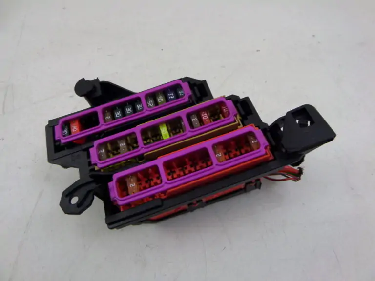
Photo of the block
Fuse Block – No. 2
The block is located at the positive terminal of the battery (only in cars with the battery in the trunk) .
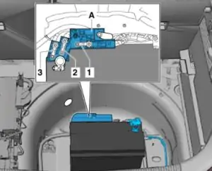
Deciphering
- Unused;
- On-board power supply / engine component power supply;
- Unused;
- Battery isolator -N253-.
Fuse Block – No. 3
Plan
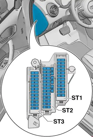
ST1 panel (black)
| 1 | 30 | Digital audio control unit -J525- Voltage regulator -J532- Radio -R- |
| 2 | 40 | Heating control unit -J65- Contact X load relief relay -J59- Fresh air blower control unit -J126- Fresh air blower -V2- |
| 3 | 20 | Car cigarette lighter socket -U1- 12 V -U5- |
| 4 | 15 | Trailer Detection Control Unit -J345- |
| 5 | 5 | Data bus diagnostic interface -J533- |
| 6 | 30 | Passenger door control unit -J387- Rear right door control unit -J389- |
| 7 | 30 | Driver’s door control unit -J386- Rear left door control unit -J388- |
| 8 | 30 | Rear window heating relay -J9- Rear window heating -Z1- |
| 9 | 25 | ABS control unit -J104- |
| 10 | 20 | On-board power supply control unit -J519- |
| 11 | 15 | High frequency horn -H2- Low frequency horn -H7- Horn relay -J413- |
| 12 | 30 | On-board power supply control unit -J519- |
Fuse No. 3, rated at 20A, is for the cigarette lighter.
ST2 panel (brown)
| 1 | 5 | Anti-theft alarm system sound signal -H12- Anti-theft alarm system sensor -G578- |
| 2 | 5 5 7.5 | Terminal 30 Power supply relay -J317- ( 22) Motronic power supply relay -J271- (21) Engine control unit -J623- |
| 3 | 5 | On-board power supply control unit -J519- |
| 4 | 515 | ABS control unit -J104- Voltage stabiliser 2 -J570- All-wheel drive control unit -J492- |
| 5 | – | Unused |
| 6 | 5 | Rain and light sensor -G397- Mobile phone amplifier -R86- Mobile phone holder -R126- Front roof module -WX3- |
| 7 | 15 20 | Fuel pump control unit -J538- Fuel pump relay -J17- ( 22) |
| 8 | 10 | Additional coolant pump relay -J496-, until October 2014 |
| 9 | 5 | Steering column control unit -J527- |
| 10 | 5 | Light switch -E1- |
| 11 | 10 | Climatronic air conditioning control unit -J255- Air conditioning control unit -J301- Passenger door control unit -J387- (up to April 2012) Right rear door control unit -J389- (up to April 2012) 16-pin connector – T16-, diagnostic connector |
| 12 | 10 | Driver’s door control unit -J386- (up to April 2012) Rear left door control unit -J388- (up to April 2012) |
| 13 | 10 | On-board power supply control unit -J519- |
| 14 | 20 | Socket relay -J807- only for vehicles without trailer coupling socket |
| 15 | 30 | On-board power supply control unit -J519- |
| 16 | 20 | Wiper motor 1 switching relay -J368-, up to October 2014 Engine components power supply relay -J757- Ignition coils 1 with output stage -N70- |
Relay Holder – No. 4
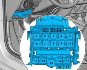
Designation
1-40-Voltage Stabilizer -J532-
2-50-Power supply of fuse block 1 -ST1- on fuse block D -SD-
3-40-Terminal 15 Power Supply Relay -J329-
4-40-ABS control unit -J104-
5-5-Voltage regulator 2 -J570-, stepper output
6-5-On-board power supply control unit -J519-, voltage regulator -J532-
16-10-Stop light switch -F- (from November 2011 to October 2014) / Clutch pedal position sensor -G476- (from November 2011 to October 2014)
17-5-Lambda probe heating element -Z19- (from November 2011 to October 2014)
Fuse Box – No. 5
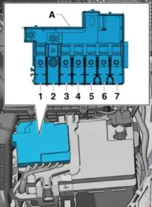
Deciphering the Scheme
- 175A – Generator -C-
- 40A – Low power heater relay -J359- / Additional air heating element -Z35-
- 110A – Power supply to on-board network/engine components
- 80A – Power steering control unit -J500-
- 50A/40A – Coolant fan thermal switch -F18- / Radiator fan control unit -J293-
- 50A – Glow plug controller -J179-
- 60A – High Heating Power Relay -J360- / Battery Monitoring Control Unit
Engine compartment fuse box – assignment
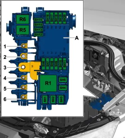
Deciphering
| 1 | Vehicle electrical system 110/50A, power supply to engine components, radiator fan control unit -J293, radiator fan -V7- |
| 2 | Alternator 250A -C-, voltage regulator -C1- |
| 3 | Battery + |
| 4 | 80A Power steering control unit -J500- |
| 5 | 50A Glow plug control unit -J179-, Glow plug 1 -Q10-, Glow plug 2 -Q11-, Glow plug 3 -Q12-, Glow plug 4 -Q13- |
| 6 | 50A Radiator fan control unit -J293-, Radiator fan -V7- |
| On-board network 125A, power supply to engine components |